
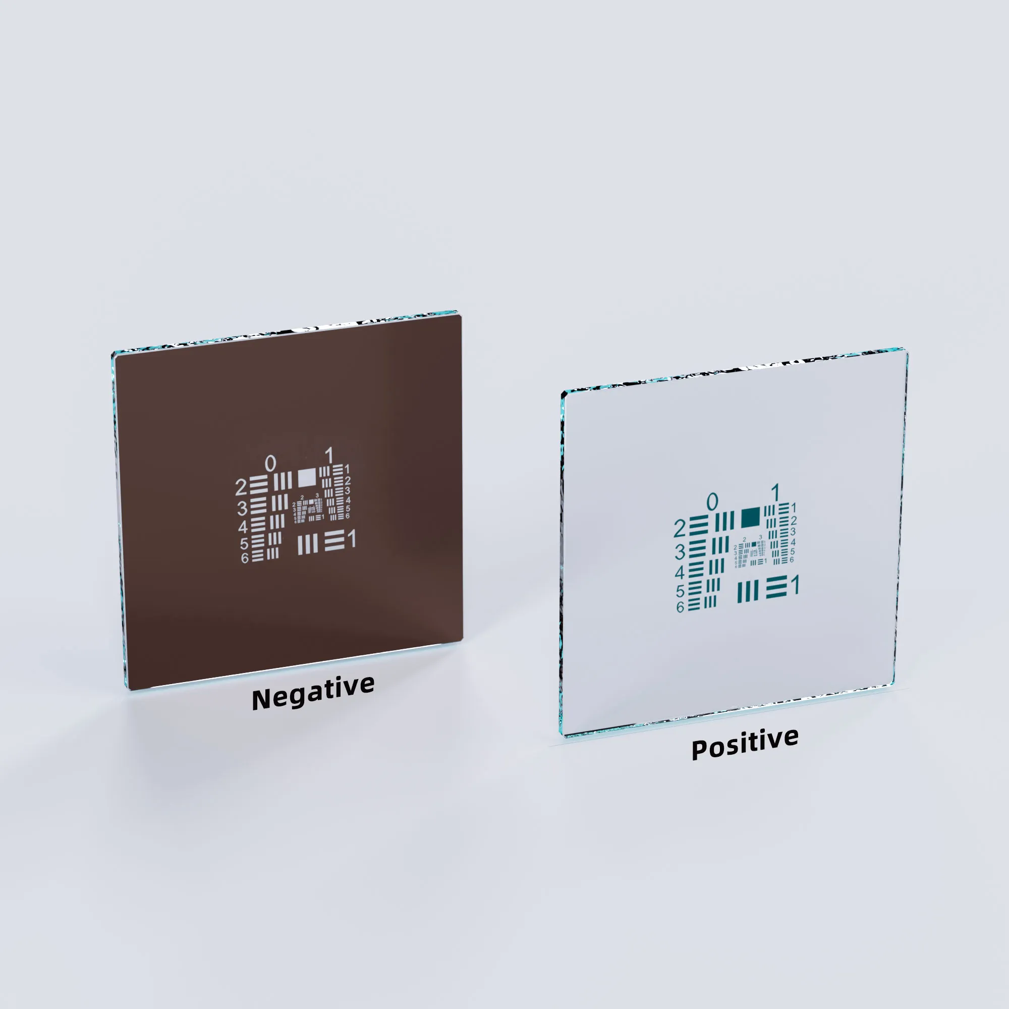
When choosing a USAF 1951 resolution test chart, first identify the optical system you need to test. Then determine the required resolution range, target material, and overall target size.
The selection process can be summarized as:
Optical System → Resolution Range → Target Material → Target Size
Camera, lens, machine vision, and microscope systems have different operating parameters. The first step is therefore to identify the system being tested and the key parameters that affect its resolution performance.
1. Choose a USAF 1951 Target Based on the Optical System
First determine whether you are testing a camera, lens, machine vision system, or microscope, and then confirm the main parameters that influence the test.
① Camera
For a camera, confirm the following three parameters:
• Sensor Resolution: Check the total pixel count and image resolution to understand how many sampling points the sensor provides.
• Pixel Size: Check the physical size of each pixel to understand the sensor sampling scale for fine image details.
• Field of View: Confirm the actual imaging area to determine how object details are represented within the full image.
Once these parameters are known, you can determine the resolution range that the USAF 1951 target needs to cover.
② Lens
For a lens, confirm the following three factors:
• Expected Resolution: Determine the level of detail the lens is expected to resolve.
• Working Distance: Confirm the actual distance between the lens and the target during testing.
• Test Conditions: Keep the camera, focus, lighting, and target position consistent when comparing different lenses.
After these conditions are defined, select a USAF 1951 pattern range that matches the expected resolving capability of the lens.
③ Machine Vision Systems
For a machine vision system, confirm the following three factors:
• Minimum Inspection Feature: Determine the smallest defect, edge, character, line, or surface feature that the system must detect.
• Field of View: Confirm the actual inspection area that must be covered in a single image.
• Working Distance: Confirm the installation distance between the camera and the object, and combine it with the lens specifications to determine the imaging scale.
These parameters help define the resolution that the complete machine vision system needs to verify.
When the specifications match your application, you can refer to the USAF 1951 Test Target.
④ Microscope Systems
For a microscope, confirm the following three parameters:
• Optical Resolution: Determine the resolution capability that the microscope system is expected to achieve.
• Objective Magnification: Confirm the objective magnification and the corresponding observation scale.
• Numerical Aperture: Confirm the NA of the objective to estimate the range of detail the microscope can resolve.
Once these parameters are known, you can select a USAF 1951 target that covers the required microscope resolution range.
When the specifications match your system, you can refer to the USAF 1951 Chrome-on-Glass Microscope Calibration Target.
2. Determine the Required USAF 1951 Resolution Range
After identifying the optical system and its key parameters, determine how much resolution range the target needs to cover.
The main specifications to check are lp/mm, feature size, and Group / Element range.
① lp/mm
lp/mm represents the spatial frequency of the USAF 1951 pattern.
• Lower lp/mm: Corresponds to coarser line patterns and lower-resolution testing.
• Higher lp/mm: Corresponds to finer line patterns and higher-resolution testing.
• Selection Method: Choose an lp/mm range that covers the expected spatial resolution of the optical system.
The highest lp/mm on the target should cover the finest resolution that the system needs to verify.
② Feature Size
Feature size represents the physical size of an individual test feature on the USAF pattern.
• Larger Feature Size: Suitable for testing larger image details.
• Smaller Feature Size: Suitable for higher-resolution cameras, lenses, and microscope systems.
• Selection Method: Determine the smallest object detail that the system needs to verify, then choose a target that includes features of the same size or smaller.
A smaller feature size allows the target to cover a finer resolution range.
③ Group / Element Range
A USAF 1951 chart organizes different pattern sizes using Groups and Elements.
• Group: Represents the main resolution level.
• Element: Further divides each Group into smaller resolution steps.
• Group / Element Range: Defines the range from coarse to fine patterns available on the target.
When selecting a chart, confirm that the highest Group and Element cover the finest pattern required by your system while still providing coarser patterns for positioning and progressive observation.
For Group / Element calculations and lp/mm conversion, see:
How to Use a USAF 1951 Test Target to Measure Optical Resolution
3. Choose the Right USAF 1951 Target Material and Size
After determining the optical system and resolution range, choose the target material and overall target size that match the actual test environment.
① Glass
Glass has three main characteristics as a target substrate:
• Rigidity: High rigidity provides stable support for the test pattern.
• Flatness: Good flatness helps maintain the geometry of the printed or deposited pattern.
• Dimensional Stability: Stable physical dimensions are suitable for repeated testing and fixed test environments.
Glass is therefore suitable for optical testing that requires good flatness, stability, and repeated use.
② Chrome-on-Glass
Chrome-on-glass is mainly selected for the optical properties of the chrome pattern:
• Fine Pattern: Suitable for producing fine USAF 1951 features.
• Optical Contrast: Chrome areas and transparent areas create clear light-and-dark pattern contrast.
• Application: Suitable for microscopes, high-magnification imaging, and higher-resolution optical testing.
When selecting a chrome-on-glass target, confirm the required lp/mm, feature size, and Group / Element range.
③ Film
Film has three main characteristics:
• Large Format: Suitable for producing physically larger targets.
• Low Weight: Its lower weight is useful for large targets and lightweight mounting requirements.
• Flexible Installation: Suitable for applications that require easier transportation, replacement, or large-area target placement.
During use, the film should remain flat and stable so that the USAF pattern maintains its intended geometry.
④ Overall Target Size
Overall target size should be determined according to the following four conditions:
• Field of View: The target should provide a suitable test area within the actual FOV.
• Working Distance: The test distance affects the target position and the area captured by the imaging system.
• Magnification: High-magnification systems usually observe a smaller area and can therefore use a more compact target.
• Mounting Space: The target dimensions should fit the available installation and adjustment space in the equipment.
Overall target size refers to the physical dimensions of the complete chart, while feature size refers to how fine the USAF patterns are. These two specifications should be evaluated separately.
4. USAF 1951 Resolution Test Chart Selection Checklist
Use the following checklist when selecting a USAF 1951 resolution test chart:
| Selection Step | What to Confirm |
|---|---|
| ① Optical System | Camera, lens, machine vision, or microscope |
| ② System Parameters | Sensor, FOV, working distance, magnification, NA, and other relevant parameters |
| ③ Resolution Range | Smallest detail the system needs to verify |
| ④ USAF Pattern | lp/mm, feature size, and Group / Element range |
| ⑤ Target Material | Glass, chrome-on-glass, film, or another suitable substrate |
| ⑥ Overall Target Size | FOV, working distance, magnification, and mounting space |
Following these steps helps you select a USAF 1951 resolution test chart that matches both the optical system and the actual testing requirements.