
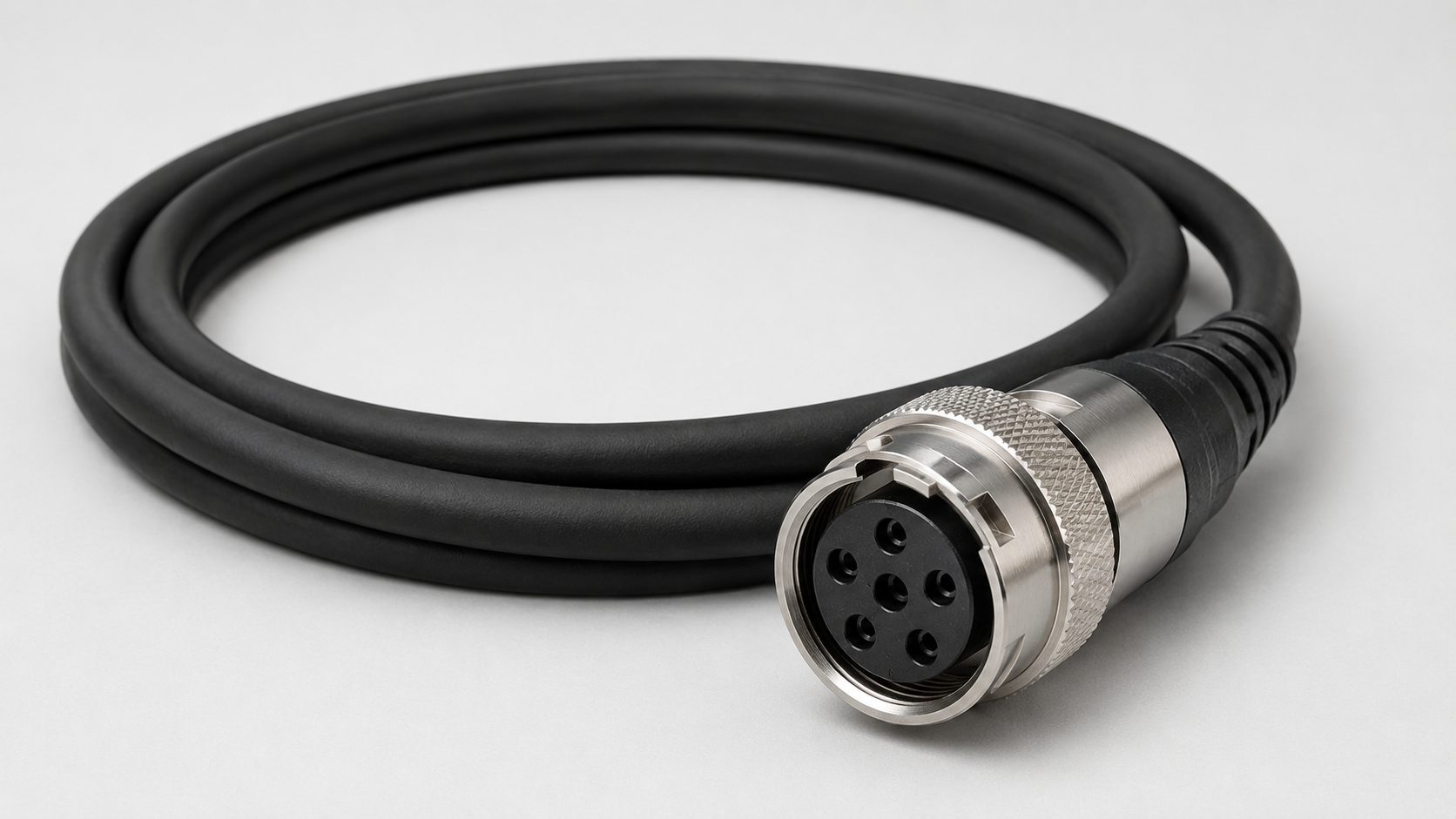
Choosing the right GigE Vision cable requires more than checking whether both ends have an Ethernet connector.
The cable must match the camera interface, Ethernet requirements, connector type, installation distance, shielding needs, mechanical locking, cable routing, and whether the cable remains fixed or moves repeatedly during operation.
For most machine vision systems, the selection process should follow this order:
Camera Ethernet Interface → Ethernet Requirement → Connector Type → Cable Length → Shielding → Mechanical Design → Motion Requirement
A cable that fits the connector but does not meet the electrical or mechanical requirements of the system can still cause installation problems or unreliable operation.
The key principle is simple:
Choose the cable around the complete camera and installation requirements—not around the connector alone.
What Is a GigE Vision Cable?
A GigE Vision cable is an Ethernet cable used to connect a GigE Vision machine vision camera to a network interface, industrial PC, Ethernet switch, or other compatible network equipment.
GigE Vision does not define a unique cable type by itself; the cable must meet the Ethernet and camera interface requirements of the system.
Depending on the camera and system design, a GigE Vision camera cable may use connectors such as:
- RJ45
- M12
- M12-to-RJ45
- Straight RJ45
- Right-angle RJ45
- Screw-locking RJ45
The connector is only one part of the cable specification.
A suitable machine vision Ethernet cable must also match the required Ethernet interface, cable construction, shielding, length, and installation conditions.
This is why two cables that both appear to be Ethernet cables may not be equally suitable for the same machine vision system.
Step 1: Check the Camera Ethernet Interface
The first step is to identify the physical Ethernet interface on the camera.
Common machine vision configurations include:
Camera → RJ45
or:
Camera → M12
If the camera uses RJ45, start with an RJ45-compatible cable.
If the camera uses M12, determine the exact M12 interface and coding before selecting the cable.
Do not choose an adapter or cable first and then try to make the camera fit the cable.
The correct order is:
Camera Interface → Compatible Cable
The device on the other end also matters.
For example, a camera may use M12 while the industrial PC or Ethernet switch uses RJ45. In that case, an M12-to-RJ45 cable may provide a direct physical connection between the two devices.
Step 2: Verify the Ethernet and Cable Requirements
After identifying the connector, verify the actual Ethernet requirements of the system.
Check:
- Camera Ethernet specification
- Required data rate
- Cable category
- Network interface specification
- Ethernet switch specification, if used
- Power over Ethernet (PoE) requirement, if applicable
- Cable length
- Complete communication-link requirements
Do not assume that a cable is suitable simply because it has RJ45 or M12 connectors.
For example, a GigE Cat5e cable may be appropriate for certain Gigabit Ethernet machine vision systems, but cable compatibility should still be confirmed from the camera, cable, and network equipment specifications.
Likewise, connector shape alone does not indicate the maximum supported Ethernet performance.
If the camera uses Power over Ethernet (PoE), verify that the camera, cable, and PoE source—such as the switch or injector—meet the required PoE specification and power requirements.
Ethernet data compatibility alone does not automatically confirm PoE compatibility.
Step 3: Choose Between RJ45 and M12
After identifying the camera interface, choose the connector configuration that matches both ends of the system.
Use RJ45 when the camera and network equipment provide compatible RJ45 interfaces.
Use M12 when the camera requires the corresponding M12 interface and coding, especially where a mechanically locked circular connection is part of the system design.
If the camera uses M12 while the network side uses RJ45, use a compatible M12-to-RJ45 configuration.
An M12 Ethernet cable must still match the required coding, keying, pin configuration, and Ethernet specification.
For a detailed comparison, see M12 vs RJ45 GigE Camera Cable: Which Connector Should You Choose?.
Step 4: Check M12 Coding Before Choosing an M12 Cable
If the camera uses M12, do not stop at the word “M12.”
Different M12 interfaces can use different coding and mechanical keying.
For example, available cable configurations may include:
M12 A-Coded 8-Pole Male to RJ45 High-Flex Ethernet Cable
and:
M12 X-Coded 8-Pole Male to RJ45 High-Flex Cable
Do not assume these cables are interchangeable simply because both use an M12 connector.
Before choosing, verify:
- Camera M12 coding
- Mechanical keying
- Pin assignment
- Cable wiring
- Ethernet requirement
The camera interface specification should always be the reference.
Step 5: Choose the Correct Cable Length
Cable length should be based on the actual routing path through the machine—not just the straight-line distance between the camera and industrial PC.
Consider:
- Cable trays
- Control cabinets
- Machine frames
- Moving axes
- Service loops
- Connector clearance
- Required routing around other equipment
A cable that is too short can create mechanical tension at the connector.
A cable that is unnecessarily long can make routing and cable management more difficult.
The best approach is to calculate the real routing distance and include only the additional length required for proper installation and motion.
The maximum usable length must also remain within the requirements of the Ethernet system and cable specification.
Step 6: Check Shielding and Industrial Noise Conditions
Machine vision systems are often installed near electrically noisy equipment such as:
- Servo motors
- Variable-frequency drives
- Robots
- Switching power supplies
- High-current cables
- Other automation equipment
Because of this, shielding can be an important factor when selecting an industrial camera Ethernet cable.
Cable performance is not determined by shielding alone.
Also consider:
- Connector shielding
- Grounding
- Cable routing
- Separation from high-power wiring
- Overall machine EMC design
A shielded cable installed poorly can still experience interference problems.
The cable should therefore be selected as part of the complete electrical installation.
Step 7: Determine Whether the Cable Will Move
A major mechanical question is whether the cable remains stationary or moves repeatedly during normal machine operation.
Examples of moving installations include:
- Drag chains
- Linear stages
- Moving camera heads
- XY positioning systems
- Automated motion assemblies
If the cable repeatedly moves, a High Flex GigE cable may be required.
If the cable remains fixed after installation, a standard fixed-routing cable may be sufficient.
This decision is independent of RJ45 versus M12.
In other words:
RJ45 / M12 → determined by interface
High Flex / Standard → determined by cable motion
For a detailed explanation, see High Flex Cables vs Standard Camera Cables: Which Is Better for Machine Vision?.
Step 8: Choose Straight or Right-Angle Connectors
Connector orientation can determine whether a cable actually fits into the available machine space.
Straight RJ45
A straight connector works well when enough clearance is available behind the camera.
For example:
GigE Cat5e RJ45 Straight High-Flex Ethernet Cable
can be suitable where the cable can route directly away from the camera.
Right-Angle RJ45
When rear clearance is limited, a right-angle configuration may provide better routing.
For example:
GigE Cat5e RJ45 90° Down High-Flex Ethernet Cable
may fit installations where the cable needs to exit downward.
However, “90°” is not enough information by itself.
Always verify:
- Connector orientation
- Cable exit direction
- Screw position
- Camera mounting orientation
- Nearby brackets or machine structures
A right-angle connector pointing in the wrong direction can be less useful than a straight connector.
Step 9: Check Connector Locking and Retention
Machine vision cameras are often mounted on equipment that may experience vibration or mechanical disturbance.
Connector retention should therefore be evaluated separately from the electrical interface.
Possible designs include:
- Standard RJ45 latch
- Screw-locking RJ45
- Horizontal screw retention
- M12 threaded locking
For example:
GigE Cat5e RJ45 Horizontal Screws High-Flex Cable
may be suitable when the camera supports the corresponding horizontal screw-locking structure.
The important rule is:
The locking design on the cable must match the mechanical interface on the camera.
A stronger-looking locking system is not useful if it cannot physically attach to the camera.
Step 10: Check the Remaining Environmental Requirements
After confirming the electrical interface, shielding, motion requirements, connector orientation, and locking method, check the remaining environmental conditions of the installation.
These may include:
- Abrasion exposure
- Bend-radius requirements
- Cable routing constraints
- Temperature requirements
- Other environmental limits specified for the machine or application
Verify that the selected GigE Vision cable meets the environmental conditions specified for the actual installation.
This final check helps ensure that a cable that is electrically compatible is also mechanically suitable for the machine.
Is a GigE Vision Cable the Same as an I/O or Trigger Cable?
No.
A GigE Vision cable primarily provides the Ethernet communication path used for image and network data.
An I/O / Trigger / Camera Power cable serves different functions, which may include:
- Trigger input
- Trigger output
- GPIO
- Strobe signals
- Sensor or PLC communication
- Camera power, depending on the camera and cable design
Some machine vision cameras may use both cable types at the same time:
GigE Vision Cable → Image / Ethernet Data
I/O / Trigger Cable → Trigger / GPIO / Control / Power as required
They should not be treated as interchangeable simply because both connect to the same industrial camera.
For detailed I/O and trigger cable selection, see How to Choose an I/O and Trigger Machine Vision Cable.
Common Mistakes When Choosing a GigE Vision Cable
Mistake 1: Choosing by Connector Shape Alone
RJ45 or M12 identifies only part of the interface. Ethernet specifications and wiring still need to match.
Mistake 2: Assuming All M12 Ethernet Cables Are Interchangeable
M12 coding, keying, pin assignment, and cable wiring must be checked.
Mistake 3: Ignoring Cable Length
The route through the machine may be significantly longer than the direct distance between the camera and network device.
Mistake 4: Ignoring Shielding and Cable Routing
Electrical noise problems cannot always be solved by changing the camera or software. Cable construction and routing matter.
Mistake 5: Using a Fixed Cable in a Repeated-Motion Application
If the cable continuously moves, its mechanical flex requirements must be evaluated separately.
Mistake 6: Choosing the Wrong Right-Angle Direction
A 90° connector can still interfere with the machine if its exit direction does not match the installation.
Mistake 7: Assuming a Locking Connector Fits Every Camera
Screw positions and mechanical locking structures must match the camera interface.
GigE Vision Cable Selection Checklist
Before choosing a cable, confirm:
- Camera Ethernet interface
- RJ45 or M12 connector
- M12 coding, if applicable
- Pin configuration
- Ethernet specification
- Cable category
- Required data rate
- PoE requirement, if applicable
- Cable length
- Shielding requirement
- Straight or right-angle orientation
- Connector locking method
- Fixed or repeated-motion installation
- High Flex requirement
- Bend radius
- Installation environment
- Connector clearance
If PoE is used, also confirm that the camera, cable, switch or injector, and required PoE specification are compatible.
If all of these conditions match the camera and machine, the risk of choosing an electrically compatible but mechanically unsuitable cable is much lower.
Conclusion: Which GigE Vision Cable Should You Choose?
The right GigE Vision cable is the one that matches both the camera’s Ethernet interface and the machine’s installation conditions.
Start with the camera connector and Ethernet specification.
Then verify:
RJ45 or M12 → M12 coding → cable category → data and PoE requirements → cable length → shielding → connector orientation → locking → fixed or moving installation
Use M12 when the camera requires the correct M12 interface. Use RJ45 when the camera and network equipment use RJ45. If the camera uses M12 while the network side uses RJ45, select a compatible M12-to-RJ45 cable.
For moving installations, evaluate High Flex separately from the connector choice.
Electrical compatibility determines whether the cable can communicate and, where applicable, deliver the required PoE power. Mechanical compatibility determines whether it can work reliably in the machine.