
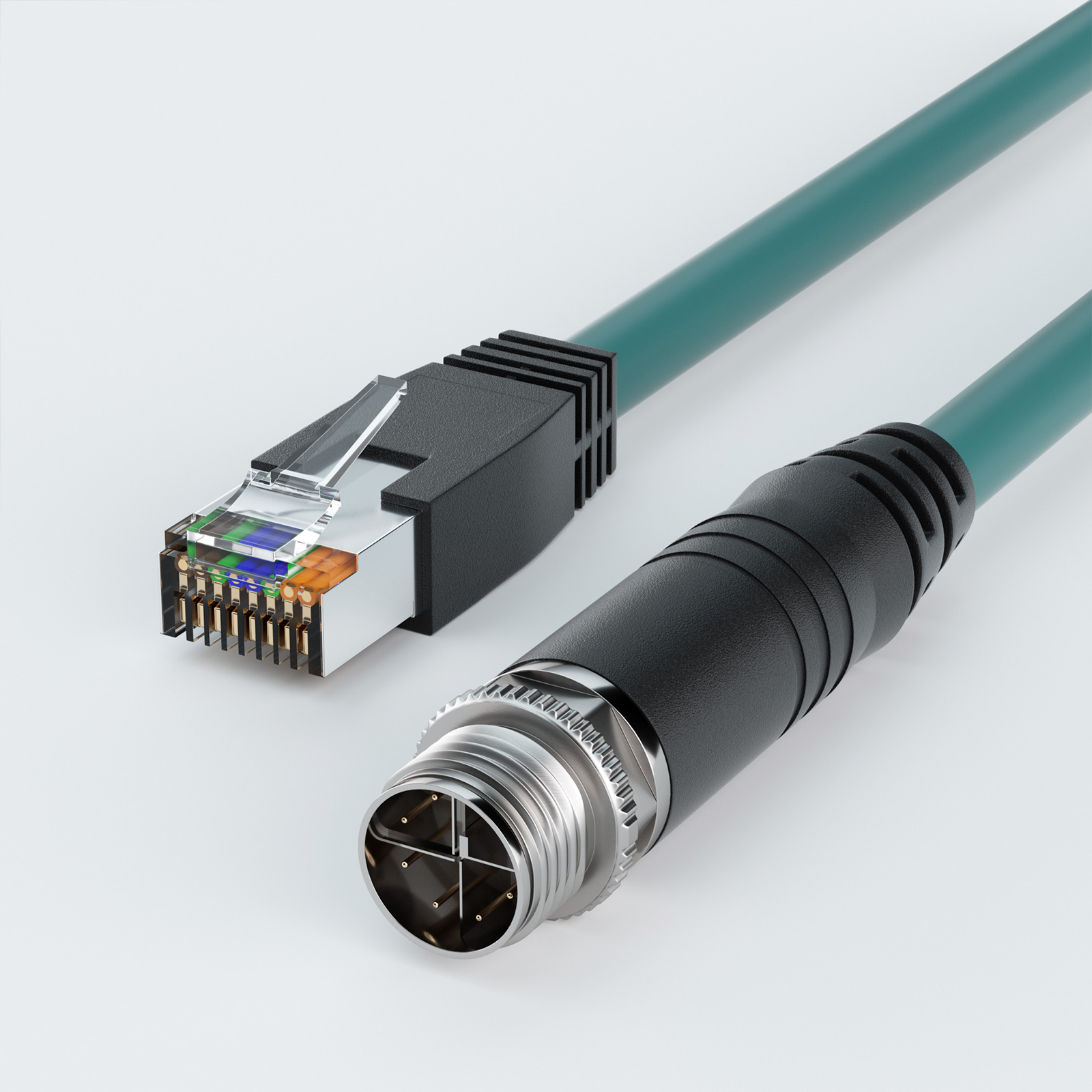
Choosing the right machine vision cable involves more than finding a connector that fits the camera.
For an I/O and Trigger machine vision cable, compatibility depends on several factors: connector type, pin count, pinout, trigger and GPIO requirements, camera power, connector orientation, cable flexibility, shielding, and installation length.
A connector may physically fit an industrial camera and still be electrically incompatible if its pin assignments are different. Likewise, a cable that works perfectly in a fixed installation may not be suitable for continuous motion in a drag chain or robotic system.
The safest selection process is:
Connector → Pinout → Trigger / GPIO / Power → Connector Orientation → Flex Requirement → Electrical Requirements → Shielding → Cable Length
This guide explains each step.
What Is an I/O and Trigger Machine Vision Cable?
An I/O and Trigger machine vision cable connects an industrial camera to external control, triggering, lighting, and power devices.
Depending on the camera and cable design, it may carry functions such as:
- Trigger Input
- Trigger Output
- GPIO
- Strobe or lighting control
- PLC signals
- Encoder signals
- Camera Power
- Ground
- Other camera control signals
This is different from a GigE, USB3 Vision, or CoaXPress data cable.
For example, in a GigE vision system, the Ethernet cable normally handles image and data transmission, while the I/O / Trigger cable may connect the camera to a sensor, PLC, lighting controller, encoder, or external power source.
So the key question is:
Does the cable correctly match the camera's I/O interface and the signals required by the vision system?
Step 1: Match the Cable to the Camera's I/O Connector
Start by checking the I/O connector specified by the industrial camera manufacturer.
Common configurations include:
- 6-pin
- 8-pin
- 12-pin
- Other multi-pin industrial connectors
The connector and pin count provide the first level of compatibility screening, but they are not enough to confirm compatibility.
When Should You Choose a 6-Pin Machine Vision Cable?
Choose a 6-pin machine vision cable when the camera uses a corresponding 6-pin I/O interface and the required Trigger, GPIO, Power, and Ground connections are available through that interface.
A typical option is a 6-pin female to open Trigger / I/O / Camera Power high-flex cable.
Before using it, verify that the cable's pin assignments match the camera manufacturer's pinout.
When Should You Choose an 8-Pin I/O Cable?
If the industrial camera uses an 8-pin I/O connector, select an 8-pin cable with the correct connector and matching pin assignment.
For example, an 8-pin female to open Trigger / I/O / Camera Power high-flex cable can be considered for cameras using the corresponding interface.
Two cameras can use similar 8-pin connectors while assigning Power, Ground, Trigger, or GPIO to different pins, so the Camera Pinout must still be checked.
When Should You Choose a 12-Pin I/O Cable?
Choose a 12-pin cable when the camera specifies a corresponding 12-pin I/O interface.
A 12-pin female to open Trigger / I/O / Camera Power high-flex cable is one example of this configuration.
A 12-pin interface provides more connection positions than a 6-pin or 8-pin connector, but the camera manufacturer's pin assignment remains the deciding factor.
Step 2: Verify the Camera Pinout and Cable Pinout
This is the most important step in I/O / Trigger cable selection.
A matching connector does not automatically mean a matching cable.
Before installation, compare the Camera Pinout with the Cable Pinout pin by pin.
Typical functions may include:
- Power
- Ground
- Trigger Input
- Trigger Output
- GPIO
- Strobe Output
- Encoder Input
- Reserved pins
For example, one camera may use a particular pin for Trigger Input while another camera with a similar connector may assign that position to a different I/O function.
The correct compatibility rule is:
The connector determines whether the cable can physically connect. The pinout determines whether it can work correctly.
Always use the manufacturer's industrial camera pinout or I/O connector documentation as the reference.
Step 3: Identify the Trigger and I/O Signals You Actually Need
Once connector compatibility is confirmed, determine what the cable must do in the application.
Start by listing the external devices connected to the camera, such as:
- Photoelectric sensors
- PLCs
- Encoders
- Proximity sensors
- Motion controllers
- Lighting controllers
- External power supplies
Then identify the required camera signals.
Trigger Input
Many machine vision systems use an external signal to control exactly when the camera captures an image.
For example:
Product arrives → sensor generates signal → camera receives Trigger Input → image is captured
If this is your application, confirm that the Trigger Input and corresponding Ground connection are available through the selected cable.
Trigger Output and Strobe Output
Some systems require the camera to synchronize with an external light or another device.
A typical sequence may be:
Camera exposure starts → Strobe Signal is generated → light activates → image is captured
In this case, check whether the required Trigger Output or Strobe Output is available in both the camera pinout and the cable wiring.
GPIO
GPIO may be required when an industrial camera needs to exchange control signals with a PLC, motion controller, automation controller, alarm, or another machine component.
Confirm both the number and function of the required inputs and outputs.
Camera Power
Some I/O and Trigger machine vision cables also carry Camera Power.
Before selecting a cable, determine whether the cable only carries I/O and trigger signals or also supplies power to the camera.
If power is carried through the same cable, voltage and current requirements become part of the cable selection process.
Step 4: Choose a Straight or Right-Angle Connector
Electrical compatibility is only part of the selection process. The cable must also fit the physical installation.
The two common options are:
- Straight connector
- Right-angle connector
When Is a Straight Connector Better?
A straight connector is usually suitable when there is enough clearance behind the camera for the cable to exit naturally.
It is a practical choice when the cable will not interfere with camera brackets, machine frames, enclosures, electrical cabinets, sensors, or other components.
When Is a Right-Angle Connector Better?
A Right-angle connector is usually better when space behind the camera is limited.
Typical applications include:
- Cameras installed close to an enclosure
- Compact inspection stations
- Cameras mounted inside machinery
- Installations requiring the cable to route along the side of the camera
- Systems where rear connector clearance must be minimized
For example, OKLAB offers different 6-pin right-angle configurations, including:
6-pin female right-angled 1 to open Trigger / I/O / Camera Power high-flex cable
and
6-pin female right-angled 4 to open Trigger / I/O / Camera Power high-flex cable
For a right-angle connector, also confirm:
- Connector key position
- Cable exit direction
- Camera mounting orientation
- Available clearance
- Nearby brackets or machine structures
A right-angle connector facing the wrong direction can still interfere with the machine even if its electrical interface is correct.
Step 5: Choose a High-Flex Machine Vision Cable for Moving Applications
A cable used in a fixed camera installation and one used in continuous motion face very different mechanical stresses.
If the camera or cable repeatedly moves, a high-flex machine vision cable should be considered.
Fixed Installation
For a stationary installation, the main selection factors are typically:
- Connector compatibility
- Pinout
- Electrical requirements
- Shielding
- Environmental conditions
- Cable length
Continuous Motion
High-flex cable becomes especially important in applications involving:
- Drag chains
- Linear stages
- XY motion systems
- Pick-and-place equipment
- Industrial robots
- Robotic arms
- Reciprocating camera assemblies
- Automated production equipment
Repeated bending can fatigue conductors and insulation over time.
An unsuitable cable may eventually cause intermittent Trigger signals, unstable I/O communication, camera power interruptions, or cable failure.
What Should You Check in a High-Flex Cable?
Depending on the available product specifications, check:
- Dynamic bend radius
- Suitability for repeated flexing
- Drag-chain suitability
- Jacket construction
- Strain relief
- Connector retention
- Flex-life rating
The bend radius deserves particular attention. Even a cable designed for repeated motion can experience premature failure if it is installed below its specified minimum dynamic bend radius.
Step 6: Check Voltage, Current, and Electrical Requirements
When the cable carries Camera Power or external I/O signals, electrical compatibility must be verified before connection.
Camera Supply Voltage
Confirm the supply voltage specified by the camera manufacturer.
The camera, power source, and cable configuration must all be compatible.
Camera Current
Voltage alone is not enough.
If power is supplied through the cable, confirm that the cable and connector arrangement are suitable for the camera's current requirement.
Trigger Signal Voltage
The output from a PLC, sensor, or controller must be compatible with the electrical requirements of the camera's Trigger Input.
Do not assume that every industrial trigger interface operates at the same signal level.
GPIO Electrical Specification
If GPIO is used, check parameters such as:
- Input voltage
- Output voltage
- Current limits
- Logic configuration
- Ground reference
The correct check is:
Camera Specification + Cable Pinout + External Device Specification
All three must agree before the system is connected.
Step 7: Consider Shielding and Signal Reliability
Machine vision systems often operate next to electrically noisy equipment, such as:
- Servo motors
- Variable-frequency drives
- Industrial robots
- Motors
- Switching power supplies
- Solenoids
- High-power wiring
Electrical interference can affect Trigger and I/O signals.
Possible symptoms include:
- Missed triggers
- False triggers
- Repeated triggers
- Exposure timing errors
- Unstable communication between the PLC and camera
For these environments, check the shielding design of the machine vision cable and follow appropriate grounding and cable-routing practices.
Signal cables should also be routed thoughtfully relative to high-power cables and other potential interference sources.
Step 8: Choose the Correct Cable Length
A machine vision cable should not automatically be selected as long as possible.
A better rule is:
Use the shortest practical cable that safely covers the complete routing path and required movement.
Measure the actual route rather than the straight-line distance between devices.
Consider:
- Camera-to-PLC routing
- Camera-to-power-supply routing
- Camera-to-trigger-device routing
- Cable trays
- Drag chains
- Machine movement
- Bend locations
- Maintenance access
- Service loops
If the cable moves with the machine, calculate the required length at the maximum travel position.
Too little cable can cause tension and connector stress, while too much cable can create unnecessary loops and complicate routing.
I/O / Trigger Cable vs. GigE Machine Vision Cable
These two cable types are often used in the same vision system, but they perform different functions.
| Cable Type | Main Function |
|---|---|
| I/O / Trigger Machine Vision Cable | Trigger, GPIO, Power, Strobe, external device control |
| GigE Machine Vision Cable | Ethernet image and data transmission |
A GigE camera may therefore use both cables at the same time.
GigE cable: connects the camera to an industrial PC, network interface, or switch for image and data transmission.
I/O / Trigger cable: connects the camera to sensors, PLCs, lighting controllers, encoders, or power sources.
They are not normally substitutes for one another.
For example, an industrial system may use an M12 X-coded to RJ45 high-flex Ethernet cable or a GigE Cat5e RJ45 high-flex machine vision cable for Ethernet data transmission, while a separate I/O / Trigger cable handles triggering and control.
I/O and Trigger Machine Vision Cable Selection Checklist
Before ordering a cable, use this checklist.
| Check Item | What to Confirm |
|---|---|
| Camera Connector | 6-pin, 8-pin, 12-pin, or another interface |
| Connector Gender | Male or Female |
| Camera Pinout | Function assigned to every required pin |
| Cable Pinout | Whether it matches the camera pinout |
| Trigger Input | Whether an external trigger is required |
| Trigger Output | Whether a synchronized output is required |
| GPIO | Number and function of required I/O channels |
| Strobe | Whether lighting control is required |
| Camera Power | Whether the cable supplies camera power |
| Voltage | Compatibility with camera and external devices |
| Current | Whether the cable supports required current |
| Connector Orientation | Straight or right-angle |
| Cable Exit Direction | Correct direction for the installation |
| Motion | Fixed or continuously moving |
| High Flex | Whether repeated bending is required |
| Shielding | Suitability for the electrical environment |
| Cable Length | Full routing distance plus appropriate allowance |
| Bend Radius | Suitable for installation and motion |
| Data Cable | Whether a separate GigE or other data cable is needed |
Common Mistakes When Choosing a Machine Vision I/O Cable
Selecting by Connector Shape Alone
A connector that fits physically is not enough. Always compare the camera and cable pin assignments.
Assuming All 6-Pin, 8-Pin, or 12-Pin Cables Are Interchangeable
They are not. Pin count does not define the electrical function of every pin.
Confusing a GigE Cable with a Trigger Cable
A GigE cable primarily carries Ethernet image and data traffic. An I/O / Trigger cable carries camera control, trigger, GPIO, strobe, or power signals.
Using a Fixed Cable in a Continuous-Motion Application
Repeated-motion systems place much higher mechanical stress on the cable. Use an appropriate high-flex cable when continuous bending is expected.
Ignoring Right-Angle Orientation
A 90° connector can point in different directions relative to the connector key. Confirm the actual cable exit direction before ordering.
Checking Voltage but Ignoring Current
When a cable supplies camera power, both voltage and current requirements must be checked.
Measuring Only the Straight-Line Distance
Real industrial routing may pass through cable trays, drag chains, brackets, and moving assemblies. Measure the actual routing path.
FAQ
Can two industrial cameras use the same 6-pin machine vision cable?
Only if the connector and pin assignments are compatible.
Two cameras may use similar 6-pin connectors while assigning Trigger, Power, Ground, or GPIO differently. Always compare the camera pinout with the cable pinout.
Is an I/O / Trigger cable the same as a GigE cable?
No.
An I/O / Trigger cable is used for control functions such as Trigger Input, Trigger Output, GPIO, Strobe, and Camera Power. A GigE machine vision cable is primarily used for Ethernet image and data transmission.
A GigE camera may use both.
When do I need a high-flex machine vision cable?
Use a high-flex cable when the cable experiences repeated motion, such as in drag chains, linear stages, robotic equipment, or reciprocating camera assemblies.
For fixed installations, continuous-flex capability may not be necessary.
Should I choose a straight or right-angle camera connector?
Choose a straight connector when there is sufficient clearance behind the camera.
Choose a right-angle connector when rear space is limited or the cable must exit along the side of the camera. For a right-angle design, also confirm the exact cable exit orientation.
Is matching the pin count enough to confirm compatibility?
No.
A 6-pin cable is not automatically compatible with every 6-pin camera, and the same applies to 8-pin and 12-pin interfaces.
The connector and pinout must both match.
Can an I/O cable also supply power to an industrial camera?
Some I/O / Trigger cable configurations include Camera Power, while others may be used only for signals.
Check the camera documentation and cable pinout to confirm the Power and Ground assignments as well as the required voltage and current.
Conclusion
Choosing an I/O and Trigger machine vision cable should follow a clear engineering process rather than a visual connector match.
Start with the camera connector and pinout, then verify the required Trigger, GPIO, Strobe, and Power functions. After electrical compatibility is confirmed, select the appropriate connector orientation, high-flex construction, shielding, and cable length for the installation.
The most important rule is simple:
A matching connector does not guarantee compatibility. The pinout must also match.
If the correct cable is unclear, provide the camera model, connector type, pinout, required signals, installation direction, and motion conditions before selecting the final cable configuration.