
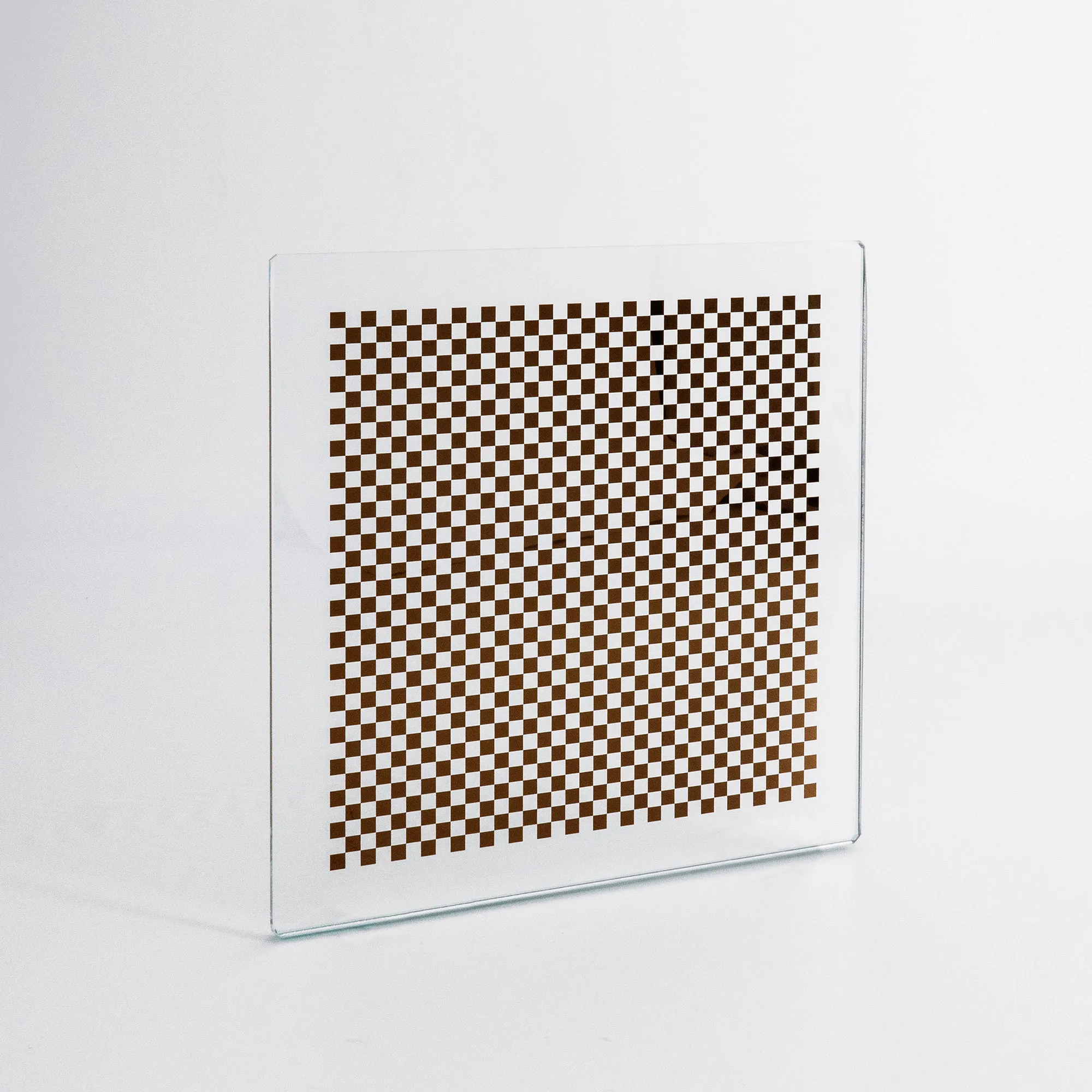
Choosing the right camera calibration pattern starts with one question:
What geometric features does your calibration software detect?
If the algorithm detects checkerboard corners, use a checkerboard. If it detects circular centers, use the required dot grid.
That decision should come before material, target size, or manufacturing accuracy.
The correct selection process is:
Software requirement → Pattern type → Pattern geometry → Feature size → Field-of-view coverage → Target construction
Checkerboard and dot grid patterns can both support accurate camera calibration, but they are not automatically interchangeable.
What Is a Camera Calibration Pattern and Why Does It Matter?
A camera calibration pattern is a geometric reference used by calibration software to estimate camera and lens parameters.
The algorithm detects known feature locations in the pattern and compares their measured image coordinates with the expected target geometry.
Depending on the calibration method, detected features may include:
- Checkerboard corners
- Circular dot centers
- Symmetric circle grids
- Asymmetric circle grids
- Other software-specific geometric features
The pattern matters because the calibration algorithm must know exactly what it is detecting.
A physically accurate target is still unsuitable if its geometry does not match the algorithm.
The first rule is therefore:
Choose the camera calibration pattern according to the software and calibration method.
Checkerboard vs Dot Grid: What Is the Main Difference?
The main difference is the type of feature detected by the calibration algorithm.
| Feature | Checkerboard | Dot Grid |
|---|---|---|
| Main detected feature | Corner intersections | Circle centers |
| Pattern structure | Alternating squares | Circular dots |
| Detection method | Corner detection | Circle / center detection |
| Common use | General camera calibration | General, industrial, or software-specific calibration when circle-grid detection is supported |
| Key geometry | Square size and corner layout | Dot diameter, pitch, and grid layout |
A checkerboard works by locating the intersections formed by adjacent black and white squares.
A dot grid works by locating the centers of circular marks.
Neither pattern is universally better.
The correct one is the pattern supported by the calibration algorithm.
How to Choose a Camera Calibration Pattern Based on Your Software
Check the calibration software before buying the target.
For a checkerboard workflow, confirm:
- Number of squares
- Number of internal corners
- Number of rows and columns
- Square size
- Pattern orientation
- Coordinate definition
For a dot-grid workflow, confirm:
- Number of rows and columns
- Number of dots
- Dot diameter
- Dot spacing or pitch
- Symmetric or asymmetric layout
- Coordinate origin and orientation
This is particularly important with software such as OpenCV and HALCON.
For example, an OpenCV workflow that uses checkerboard corner detection should use a compatible checkerboard configuration.
An OpenCV Checkerboard Camera Calibration Target on Ceramic may be suitable when its checkerboard geometry and substrate match the application.
Another option is an OpenCV Checkerboard Camera Calibration Target when its dimensions and pattern definition match the calibration setup.
For a HALCON workflow that uses a defined dot calibration pattern, a HALCON Dot Calibration Target may be appropriate when its geometry matches the procedure being used.
The buying sequence should be:
Check the software first, then specify the target.
When Should You Choose a Checkerboard Calibration Pattern?
Choose a checkerboard when the calibration algorithm detects corner intersections.
Checkerboards are commonly used for:
- Camera intrinsic calibration
- Lens distortion calibration
- Stereo-camera calibration
- Machine vision development
- OpenCV-based calibration workflows
Checkerboard corners provide distinct intersection features that can be detected and localized reliably when image contrast and resolution are sufficient.
A checkerboard is especially practical when:
- The software explicitly supports checkerboard detection
- Internal corners can be clearly resolved
- The target can occupy a useful part of the field of view
- The pattern remains flat enough for the required accuracy
Choose a checkerboard when its geometry matches the calibration algorithm and imaging setup.
When Should You Choose a Dot Grid Calibration Pattern?
Choose a dot grid when the calibration algorithm detects circular feature centers.
Dot grids are commonly used in:
- Industrial camera calibration
- Machine vision systems
- HALCON-based workflows
- Calibration methods designed around circle centers
- Applications requiring a defined symmetric or asymmetric dot layout
A dot target is appropriate when the software explicitly expects:
- Dot centers
- A particular dot spacing
- A specific row and column layout
- A specific symmetric or asymmetric pattern
Choose the dot grid required by the algorithm rather than assuming dots are inherently more accurate.
Symmetric vs Asymmetric Dot Grid: Which One Should You Use?
Use the layout required by the calibration algorithm.
A symmetric dot grid places dots in regularly aligned rows and columns.
An asymmetric dot grid offsets alternating rows or columns so that the pattern has a distinct geometric arrangement.
These layouts are not automatically interchangeable.
If the software expects an asymmetric grid, using a symmetric target can prevent correct detection or cause the geometry to be interpreted incorrectly.
Before ordering a dot target, confirm:
- Symmetric or asymmetric layout
- Dot count
- Row count
- Column count
- Dot diameter
- Dot pitch
- Coordinate convention
The rule is simple:
Do not substitute one dot-grid layout for another unless the software explicitly supports both.
Does Checkerboard or Dot Grid Give Better Calibration Accuracy?
Neither pattern is automatically more accurate in every system.
Calibration accuracy depends on the complete calibration process, including:
- Target manufacturing accuracy
- Target flatness
- Feature detection quality
- Camera resolution
- Lens distortion
- Focus
- Image contrast
- Feature size in pixels
- Number of calibration images
- Distribution of calibration poses
- Calibration algorithm
Therefore:
Choose the pattern that the algorithm can detect accurately and consistently under the actual imaging conditions.
Pattern type alone does not determine final calibration accuracy.
How Should You Choose Pattern Size, Feature Size, and Feature Count?
Three specifications need to be considered together:
Overall pattern size
Individual feature size
Number of features
For a checkerboard, consider:
- Number of rows and columns
- Number of internal corners
- Square size
- Overall pattern dimensions
- Number of pixels covering each square
For a dot grid, consider:
- Number of dots
- Dot diameter
- Dot pitch
- Number of rows and columns
- Number of pixels covering each dot
If features are too small in the captured image, detection may become unstable.
If features are too large, the image may contain too few calibration points.
The correct balance is:
Features must be large enough for reliable localization, while the pattern must still contain enough distributed features for useful calibration coverage.
This means overall target size and feature size should not be selected independently.
How Much of the Camera Field of View Should the Pattern Cover?
The calibration pattern should be captured across the center, edges, and other image regions that need to be calibrated, rather than remaining only near the image center.
A target that occupies only the center provides limited information about the outer parts of the image.
This is especially important when calibrating:
- Lens distortion
- Wide-angle lenses
- Large fields of view
- Stereo systems
- Measurement systems
When the calibration method supports multiple images or target poses, capture the pattern at different positions and orientations so that calibration features are distributed across the relevant image area.
A target that is too small for the field of view may not provide enough spatial coverage.
A target that is too large may not fit completely inside the image when the calibration procedure requires the full pattern to remain visible.
Choose target size based on the actual:
- Field of view
- Working distance
- Lens
- Sensor size
- Calibration procedure
When Do You Need a Custom Camera Calibration Pattern?
Use a custom camera calibration pattern when a standard target cannot match the required software geometry, feature size, overall dimensions, or mounting format.
Customization may be required for:
- Non-standard rows or columns
- Custom checker square size
- Custom dot diameter
- Custom dot spacing
- Unusual overall dimensions
- Special pattern geometry
- Specific substrate material
- Special mounting requirements
For example, a large-field system may require a larger pattern, while a high-magnification system may require finer features.
A Custom Film Test Calibration Target may be considered where a customized larger or lightweight format is appropriate.
For rigid custom constructions, glass- or ceramic-based targets may also be relevant when their specifications match the application.
Define the software geometry before specifying a custom physical target.
Which Camera Calibration Pattern Should You Choose for Different Applications?
The following table provides a practical starting point.
| Application | Recommended Pattern Direction | Main Selection Reason |
|---|---|---|
| OpenCV camera calibration | OpenCV-supported checkerboard or other supported pattern | Match OpenCV detection method |
| HALCON calibration | HALCON-supported dot or calibration pattern | Match HALCON pattern definition |
| Lens distortion calibration | Software-supported checkerboard or dot grid | Good image coverage |
| Stereo vision | Pattern supported by the stereo-calibration workflow | Reliable common feature detection |
| Industrial machine vision | Algorithm-compatible checkerboard or dot pattern | Stable detection under production conditions |
| Robotics | Algorithm-compatible calibration pattern | Pose and coordinate estimation |
| Wide-field calibration | Supported pattern with sufficient physical size | Better FOV coverage |
| High-magnification imaging | Fine pattern with suitable feature dimensions | Reliable sampling of small features |
Common Mistakes When Choosing a Camera Calibration Pattern
Mistake 1: Buying the Target Before Checking the Software
Confirm the supported pattern first.
Mistake 2: Treating Checkerboards and Dot Grids as Interchangeable
They use different detected features and may require different algorithms.
Mistake 3: Confusing Square Count With Internal Corner Count
Calibration software may ask for internal corners rather than the total number of printed squares.
Mistake 4: Choosing the Wrong Dot-Grid Layout
A symmetric pattern should not replace an asymmetric pattern unless the algorithm supports both.
Mistake 5: Making Features Too Small
Squares or dots that occupy too few image pixels can be difficult to localize reliably.
Mistake 6: Using Too Few Features
Very large squares or dots may reduce the number of useful calibration points.
Mistake 7: Using a Pattern That Covers Only the Image Center
Poor field coverage can limit calibration quality, particularly for lens-distortion correction.
Mistake 8: Assuming One Pattern Is Always More Accurate
Accuracy depends on the complete imaging and calibration system.
Mistake 9: Changing the Physical Pattern Without Updating Software Parameters
The software geometry must match the actual target geometry.
Camera Calibration Pattern Selection Checklist
Before ordering a camera calibration pattern, confirm:
- Which calibration software will be used?
- Which calibration algorithm will be used?
- Does it require a checkerboard or dot grid?
- If using dots, is the layout symmetric or asymmetric?
- How many rows and columns are required?
- How many internal corners or dots are required?
- What square size is required?
- What dot diameter is required?
- What dot pitch is required?
- What is the overall pattern size?
- What is the camera field of view?
- What is the working distance?
- How many pixels will cover each feature?
- Will the pattern cover enough of the image?
- Is the target flat enough for the required accuracy?
- Is a standard pattern sufficient?
- Is a custom pattern required?
Answer these questions before purchasing the target.
Conclusion: Checkerboard or Dot Grid—Which Should You Choose?
The decision is straightforward:
Choose a checkerboard when the calibration algorithm detects checkerboard corners.
Choose a dot grid when the calibration algorithm detects circular centers and requires that grid layout.
After selecting the pattern type, determine:
Rows and columns → Feature size → Pattern size → FOV coverage → Target construction
The correct camera calibration pattern is the one that matches the software, calibration algorithm, imaging geometry, and required calibration performance.